Rubik magic cube
Top sales list rubik magic cube
No results found
Latest Offers
Pakistan (All cities)
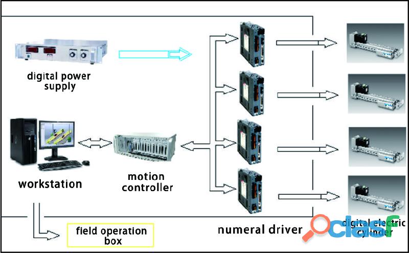
Overview In order to meet the needs of producing various specifications of continuously cast products, shorten the time for replacing the mold, and improve the production capacity and production efficiency of the continuous casting machine, the mold online width adjustment system is the key technology for efficient continuous casting. The online mold width adjustment system enables the two narrow sides of the continuous casting slab mold to move inward or outward in small steps until the predetermined width is reached. During the production process, the adjustment of the mold’s width can be completed without stopping the machine. Generally, the online width adjustment of the mold needs to be connected with the online taper measurement of the mold. Only with adjustment and detection can the online adjustment range of the mold be accurately controlled. Fig 1 Mold online width adjustment system The components of the system Workstation: host system, system width adjustment control, taper detection. On-site operation box: real-time display of the current control status, manual operation to adjust parameters. Digital Electric Cylinder: Precise digital control of electro-hydraulic drive cylinder, which can achieve high-precision quantitative control. On-line measurement of taper: Install it on the narrow-face copper plate of the mold, and monitor the taper of the narrow-face copper plate in real time. Cooperate with the detection feedback control of the width adjustment system, so as to achieve high-precision adjustment. FIG 2 System block diagram The technical parameters Adjustable range: 0-1250mm (unilateral) Control accuracy: 0.02mm/0.05mm/0.1mm Step resolution: 0.01mm/0.02mm Running speed: 0-10mm/s Power: 3.5KWl 16-bit encoder: 65536 pulses Weight: 25Kg Shell: high-strength aluminum alloy FIG 3 Syetem software interface The functions of the system Realize online width adjustment function Realize the online real-time monitoring function of mold taper Continuous casting production adjustment and non-stop production One-key operation in the main control room, automatic completion High adjustment accuracy and fast speed The interlock control of the continuous casting steelmaking system can realize automatic steel pouring
Rs 0,0
See product
3 photos
Lahore (Punjab)
8 Months Training program covering Basic Positioning, Music Theory & Fundamentals, Music Language/Notations/Sheet Music Reading & Playing, identification of pitch and different Rhythm Patterns.
Rs 10.000,0
See product
Pakistan (All cities)
Overview The continuous casting vibration type ladle slag detection device is used to detect the slag content of the ladle nozzle in the steelmaking continuous casting process, so as to improve the cleanliness of the tundish molten steel and obtain the best yield of the ladle molten steel. The device adopts the principle of vibration detection. The LAG-S200 continuous casting ladle slag automatic detection system is developed by Wuhan CenterRise M&C Engineering Co., Ltd. after many years of research with many scientific research institutes, and fully combined with the actual situation on site. It has a real field application value as a continuous casting ladle slag automatic detection system. The meaning of the system 1. Reduce the amount of tundish slag 2. Improve the purity of molten steel 3. Improve the life of the tundish 4. Reduce sliding nozzle erosion 5. Reduce nozzle blockage 6. Increase continuous pouring heats 7. Reduce the amount of residual steel in the ladle when high-quality steel is casting 8. Improve the yield of molten steel 9. Improve the quality of continuous casting billets In order to improve the purity of the molten steel in the tundish, and improve the quality of the casting billet, especially to improve the quality of the billet in the transition section, and reduce the amount of residual steel in the high-quality ladle, and prolong the life of the tundish lining, and increase the continuous casting heats, it’s necessary to detect and control the slag in the later stage of continuous casting ladle casting. The working principle The LAG-S200 continuous casting ladle slag automatic monitoring system detects the slag state during the pouring process by receiving the vibration signal of the mechanical operating arm of the ladle nozzle. In the process of molten steel pouring, when molten steel flows through the long nozzle and pours into the tundish, the molten steel impacts the wall of the long nozzle and causes the vibration of the mechanical operating arm used to support the long nozzle. Since the specific gravity of the steelmaking slag is less than half of the specific gravity of the molten steel, it floats on the surface of the molten steel, and the steelmaking slag appears when the molten steel is about to be all poured. At this time, due to the high viscosity and poor fluidity of light steelmaking slag, the impact force of the mixed flow of molten steel and steel slag on the wall of the long nozzle is quite different from that of pure molten steel. The system mainly monitors the ladle slag of the continuous casting by measuring and analyzing the vibration difference of the mechanical operating arm. The vibration signal is connected to the operation control unit of the system control cabinet through the front-stage conditioning and amplification module through the sensor installed in the middle of the operating rod. After processing, it is output to the industrial computer for operation and analysis. The slag signal detected by the system is output from the system control cabinet to the front-end control unit, and then control the alarm horn and alarm light to work, or issue an instruction to close the ladle nozzle. The features of the system (1) It is easy to install, basically no modification is made to the field equipment, and the installation and debugging work will not affect the normal production of the enterprise. (2) The detection accuracy is high, and the effective rate is greater than or equal to 95%. The threshold of slag volume is accurately set, the output control function is powerful. It has excellent performance in technical indicators such as the sensor service life and sensor usage times. (3) The sensor is installed at a position far away from the molten steel, and is cooled by a special refrigeration device for 24 hours. The outer layer adopts a composite protection structure, which has a long service life. (4) Adopt professional and targeted signal processing methods to obtain the vibration characteristic parameters of the ladle slag, and analyze, reason and judge the effective slag signal through the vibration signal database, which has a high accuracy of slag alarm. (5) The architecture is established based on the artificial intelligence network, which has the functions of self-learning and self-induction. (6) The equipment adopts a modular design. The failure of each module will not affect other parts, which ensure more reliable operation of the system and easy maintenance. (7) The alarm display device is used on site to visually indicate the flow state of molten steel and slag. When slag carryover strats, we can choose automatic mode or manual mode. In both modes, the system will give audible and visual alarm signals to remind on-site operators. (8) The system has a powerful database function. Including the comparison function for last two ladles of casting time record, the system automatically stores the running data, and generates a record file every day. (9) The system has the function of automatically controlling the ladle nozzle. The control unit is an auxiliary system of the system, which is interconnected with the ladle slag detection system to automatically control the opening of the ladle nozzle and realize the whole-process control of the liquid level of the molten steel in the tundish. The composition of the system The LAG-S200 slag detection system consists of: vibration detection sensor, pre-signal amplifier, slag detection operation unit, tundish liquid level control unit, on-site operation indication box, and process control cabinet. 1. Vibration detection sensor: It is installed on the robotic arm of the stopper to detect the vibration signal of the whole casting process of the ladle. 2. Pre-signal amplifier: Amplify, convert and transmit the weak vibration signal detected by the vibration detection sensor. 3. Slag detection operation unit: Analyze, judge and discriminate the vibration signal to realize the discrimination of all steel, mixed slag and full slag , and output the slag alarm signal. 4. Tundish liquid level control unit: Accept the control signal of the tundish nozzle and the ladle nozzle, and realize automatic or manual control to the ladle slag according to the requirements. 5. On-site operation instruction box: Provides man-machine exchange for slag alarm indication, fault indication, system activation mode selection, and control mode selection. 6. Process control cabinet, providing power management, displaying man-machine interface and setting management. The parameters of the system 1. The system controls the slag inclusion in molten steel with high precision and closes the nozzle in real time. 2. Improve the quality of steel, reduce defective products, and improve the yield. 3. The yield of molten steel is increased by 0.3%-0.5%. The nozzle can be automatically closed, so that the disadvantage of untimely manual response is overcome and less molten steel remains in the ladle. The threshold value of molten steel (slag threshold) is set by the user within a wide range. 4. No artificial factors are involved, high reliability, good repeatability or consistency. 5. The steelmaking slag does not pass through or rarely flows into the tundish, which increases the service life of the refractory material and the sliding nozzle. 6. Reduce the blockage of the tundish nozzle and increase the number of continuous pouring heats of the tundish.
Rs 200.000,0
See product
3 photos
Pakistan
due to a change in personal circumstances and a increase in work hours i am unfortunatly having to look for a new home for my four year old female beagle, jessie. Jessie has been spayed and is a member of the family it has been a very difficu....
Rs 200,0
See product
Pakistan (All cities)
Elevate yourself with ultra luxurious apartments by Risinia Skyon Bachupally gated community project. Risinia is offering 2 and 3BHK Gated Community flats in Bachupally Hyderabad. Book a Dream Home Now!
Rs 5.599,0
See product
Pakistan (All cities)
Overview The WGS-L200 Laser Slab/ Plate Steel Width Measuring System adopts the principle of double laser triangulation reflection to process the online measurement of the steel plate on the roller bed, and combines the high-speed digital signal processing technology and programming software to process the signal correspondingly, and displays the relevant data and measurement curve, so as to realize the accurate control for steelmaking process during the production. The WGS-L200 Laser Slab/Plate Steel Width Measuring System is mainly composed of computing processing software and hardware systems such as testing equipment, computing equipment. The hardware system consists of 2 sets of laser triangulation rangefinding system, on-site signal acquisition and transmission system, operation unit, host analysis and control alarm system, etc. The software of WGS-L200 laser slab/ plate steel width measuring system mainly includes data acquisition and analysis, alarm software and data visualization operation software in the host system. The data analysis system analyzes and converts the data transmitted by the signal acquisition and analysis system into the visual data of the main control room, and completes the width measurement monitoring work in the slab production operation through the set alarm threshold. The measuring principle of the system The WGS-L200 Laser Slab/Plate Steel Width Measuring System is mainly composed of computing processing software and hardware systems such as testing equipment, computing equipment. The hardware system consists of 2 sets of laser triangulation rangefinding system, on-site signal acquisition and transmission system, operation unit, host analysis and control alarm system, etc. The software of WGS-L200 laser slab/ plate steel width measuring system mainly includes data acquisition and analysis, alarm software and data visualization operation software in the host system. The data analysis system analyzes and converts the data transmitted by the signal acquisition and analysis system into the visual data of the main control room, and completes the width measurement monitoring work in the slab production operation through the set alarm threshold. The features of the system 1. Using the principle of laser triangulation reflection, it is very suitable for dynamic measurement, and the dynamic measurement accuracy is high. 2. Non-contact type, namely, the laser rangefinding sensor is installed on the upper and lower sides of the strip conveying guide groove, and the width measurement device is not in direct contact with the strip. 3. Continuous and fast sampling measurement, the sampling frequency is 300Hz-2000Hz. The measurement frequency can be set freely to realize high-speed width detection. 4. It can effectively identify and compensate the beating, inclination, side deflection and profile of the tested plate; 5. Excellent mathematical model realizes accurate width detection of the bad profile; 6. The software interface is good, powerful, easy to operate and maintenance-free; 7. The software has self-diagnosis function; 8. Full digital detection, automatic calibration system; 9. High measurement accuracy and fast response; 10. Using optical fiber signal transmission; 11. Quality control alarm; The technical parameters Measuring distance: 0.5-0.8m (according to the on-site environment) Resolution: ±0.1mm Repeatability: 0.2mm Measurement output frequency: 100-3KHz Laser class: 2 (IEC60825-1:2014) Protection class: IP65 Communication method: TCP/IP communication
Rs 0,0
See product
Pakistan (All cities)
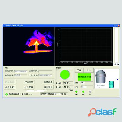
Overview The infrared converter slag detection system uses a far-infrared thermal imager to monitor the situation of converter tapping in real time, and is connected to the main control computer in the electrical room through the conversion and transmission of video signals. The radiation intensity in the infrared wavelength range of 7-14um is different to distinguish molten steel and slag. In the later stage of the converter tapping, the molten steel gradually decreases, and the steelmaking slag is involved in the molten steel and flows out of the tapping hole. After the thermal imager recognizes the steelmaking slag in the imaging temperature measurement, it will give an alarm according to the slag content ratio threshold set by the software. The thermal imager will start the slide plate to close the tapping hole, so as to realize the control of the slag in the converter tapping, and ensure the maximum yield of molten steel and the minimum control of the steelmaking slag content. The effect of slag detection in converter tapping is of great significance to the control effect of the slag amount. The converter slag detection and control system developed by our company conducts non-contact monitoring of the tapping steel flow through the far-infrared detector thermal imager. It can detect the slag condition in real time and output an alarm signal and control system, which can replace manual visual inspection and provide accurate, efficient and stable slag detection effect. When the system finds the slag, the intelligent control unit quickly makes a judgment of lifting the furnace and blocking the slag and outputs an alarm signal. As shown in Figure 1, the system includes thermal imager, front purge protection box, front electrical box, power distribution cabinet, main control monitor, monitor of rocking furnace chamber, sound and light alarm, infrared converter slag monitoring software system, etc. The features of thermal imager 1. The temperature measurement range is 200°C ~ 2000°C, high temperature measurement accuracy, and multiple temperature measurement intervals can be set. 2. High-resolution thermal imaging system, the imaging picture is clear, and the imaging color can be freely marked according to the set temperature. 3. With hot zone alarm function, the alarm zone and temperature range can be set arbitrarily. 4. With hot zone tracking function 5. Equipped with special 7~14um infrared filter lens The technical parameters 1. Temperature measurement range: 200°C ~ 2000°C 2. Temperature measurement accuracy: 2% 3. Detection accuracy and alarm accuracy: ≥98% 4. Resolution: ≥ 0.5℃ 5. Pixels: 640x240PT 6. Band: 7~14um 7. Field of view: 7.5°×5.5° 8. Frame rate: ≥ 25 frames/sec 9. Equipment service life: ≥5 years 10. The normal operation rate of the automatic control system: ≥99%
Rs 0,0
See product
3 photos
Pakistan (All cities)
Overview LDT-I200 is a new generation of converter lining thickness gauge launched by our company. The system equipment emits a pulsed laser beam to the lining surface of the converter, and receives the returned laser light to measure its flight time. Then the system equipment calculates the distance between the equipment and the target point according to the transmission speed of the laser. During measurement, the user pushes the equipment to a certain position on the platform in front of the converter, and the equipment can start to scan and measure the target area of the converter after the equipment performs rapid self-positioning. The Measuring principle The measurement speed of LDT-I200 can reach up to 2,000,000 points per second, and each scan can obtain distance data of more than 1.5 million points. The actual surface curve of the entire converter lining can be obtained by combining the measurement data of different positions and angles. During the measurement, the laser head of the equipment rotates at a certain step angle to rapidly change the angle of the pulsed laser beam. Within 4 minutes, the three-dimensional surface contour of the converter lining can be formed, and the thickness information of the furnace lining can be obtained through coordinate conversion calculation. The measurement accuracy up to ±2mm. In order to convert the distance from the internal point of the converter to the thickness gauge into the thickness of the furnace lining at each point, we must know the coordinate relationship between the trolley and the converter. We use the second laser head to position the trolley. When the trolley is pushed to the measurement site, the positioning laser head rotates at high speed to scan the three reflective strips opposite the converter. Through triangulation measurement and calculation, we can calculate the relative position of the trolley to the reflective strips. The coordinates of the reflective strip and the converter are known through mapping, so that the coordinates of the trolley relative to the converter can be accurately obtained. The main components 1. Laser measuring head 2. Wireless communication 3. Battery pack 4. Mobile laser thickness gauge host 5. Converter inclination measurement system 6. Cooling circulation system 7. Positioning auxiliary reflector 8. Laser positioning system The technical indexes Laser reproducibility: ±2mm Laser accuracy: ±2mm Local fastest measurement time: 15s Positioning time: 30s Full image measurement time: 4min The highest measurable lining temperature: 1850℃ Measuring distance: 0.5-25m Actual points are measured per frame: 1500000 points Continuous working time after fully charged: ≥3h Eye-safe laser: Class 1 laser product (doesn't hurt the eyes) The parameters of laser measuring head Measurement principle: According to the flight time and speed of the laser to calculate the distance Laser reproducibility: ±2mm Laser accuracy: ±2mm Scan rate: 2000000 points/second Measuring angle: vertical ±40°, horizontal 360° Maximum measurement temperature: 2200℃ Working temperature: -20℃-80℃ Cooling method: Integrated liquid cooling system, IP64 grade protection Laser wavelength: 1550nm (near infrared)
Rs 0,0
See product
2 photos
Pakistan
I have available 2 stunning BSH blue kittens. 1 girls and 1 boys. Mum and dad are beautiful blues and are GCCF registered. Mum has a wonderful personality, she is friendly and extremely loving. she has an excellent 4 generations pedigree.
Rs 5.000,0
See product
Pakistan (All cities)
Overview: LGK-S107 analog heat source instrument (heating tool) is independently developed and designed by Wuhan CenterRise M&C CO., Ltd. This instrument is a heating and testing equipment used to test the performance of the thermocouples installed in the mold in continuous casting machine. After the installation of the mold breakout prediction thermocouples completed, the analog heat source instrument is used to test these thermocouples before they go online. After the thermocouple is connected to the mold thermocouple detector, the current temperature of each thermocouple point will be displayed. By using our heating device to heat the copper plate point of each thermocouple at a fixed point, the thermocouple will have a synchronous temperature rise and then we can observe the temperature rise curve of the same column of temperature points to see whether the temperature measurement consistency of the column of thermocouples is consistent, so as to judge the overall status of thermocouples installed in the mold. If an abnormal point occurs, it needs to be repaired and replaced, so as to ensure the stable operation of the mold breakout prediction system. The working principle: The heating tool generates high heat by 220v alternating current and the electric heating element. The heat is transmitted to the copper plate of the mold through the copper head to simulate the heat source of molten steel, so that the thermocouples of the mold can sense the temperature change to achieve the purpose of calibrating the temperature measurement system. The composition: Walking trolley mechanism Preloader Pure copper heating contacts PID thermostat High power heating tube high power driver The parameters: Power supply: AC220V 50Hz Total power: 2200W Single point power: 300W Temperature control accuracy: 1°C Temperature control range: 0°C-500°C Common temperature range: 25°C-300°C Heating points: 3 (points can be customized) Heating method: heating tube heating Heating contact material: copper
Rs 0,0
See product
3 photos
Pakistan (All cities)
We have the Outboard Boat Engine OXE. Yamaha We are specialized in the sales of full metal scrap/ recycling material such as ac/fridge compressor , Ceramic Cpu Gold Processor Scraps , H.M.S 1&2, Copper wire scrap,Drained Battery Lead scrap in the UK (LONDON).We have all our product fully ready for sales in good quantity and quality also to be shipped out for our buyers.For Booking : https://wa.link/og0sgp Whatsapp: +15806151130
Rs 150.000,0
See product
2 photos
Pakistan (All cities)
The composition of the system The photoelectric strip automatic center position control system is mainly composed of sensors, amplifiers, PLC controllers, hydraulic control and other parts. System composition block diagram The main technical parameters 1. Detection width: 300-2800mm 2. Detection light source: 220VAC. (100VAC) 30W. High frequency white light works continuously 3. Photodetector: precision die-casting components, time constant 20ms 4. Maximum working voltage: 50VDC 5. Distance from receiver to emitter: 300-1000mm 6. Operating temperature: 0℃-60℃ 7. Resolution: 0.5mm 8. Linearity: ±1%F.S (after linearization) 9. Repeatability error: △R1%, F.S 10. Servo-valve working signal: ±10V 11. Rated pressure (oil pressure): 4.5Mpa 12. Rated flow: 30L/min 13. Symmetry: 10%
Rs 0,0
See product
2 photos
Pakistan (All cities)
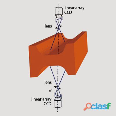
Overview The surface quality inspection of high temperature cast product is of great significance to the repair of cast product’s defects and the hot delivery of hot cast product. The ZSQ-T series of online surface quality inspection equipment for casting billets developed by Wuhan CenterRise M&C Engineering Co., Ltd can detect the defects such as scratches, cracks, holes, pits, edge cracks, edge defects on the surface of the cast products, and meet the customer's requirements for the quality inspection of the surface of the cast product. The principle of the system The ZSQ-T200 online surface quality inspection system for continuously cast products adopts the principle of optical imaging and uses a CCD image sensor to input the surface image of the cast products to be detected into the computer, and then the obtained image is processed by special image processing software to find out whether there is any defect in the image. After the defects in the image are obtained, the obtained defects are classified through a special self-learning system, and finally the requirements of the computer to automatically identify the surface defects of the cast products are achieved. The composition of the system 1. Optical part: The optical part is composed of multiple fixed-focus lenses and linear CCD, which mainly realizes scanning and imaging of the surface of the cast products. 2. Lighting part: The lighting part is composed of a high-brightness LED array and a cylindrical lens, which realizes high-brightness and high-uniformity lighting on the surface of the cast products. 3. Mechanical structure part: The mechanical structure part mainly realizes the adjustment, installation and fixing of the optical part and the lighting part, and consists of the imaging head (optical part), light box (lighting part), bracket and control cabinet. The structure is required to be stable and reliable. 4. Real-time processing: The real-time processing part is completed by the multi-CCD data real-time sampling processing unit (high-speed DSP) independently developed by Wuhan CenterRise M&C Engineering Co., Ltd. 5. Hardware part: The hardware part consists of high-speed storage controller and storage hard disk array, Gigabit InternetMAC controller, Gigabit Ethernet PHY. Rj45, and multiple high-speed workstations. 6. Detection software: The detection software mainly realizes the functions of collection, storage, transmission, processing of CCD scanning images, extraction of defects, analysis of defect characteristics, calculation of defect size and position, storage of defect images, generation of cast product’s surface quality analysis reports. etc.
Rs 0,0
See product
Pakistan
4 year old male beagle called 'Bizol' who is very sweet a little shy but once settled is very loving and friendly. He is great with other cats and dogs, he would be fine to be rehomed with older children purely as he's a little shy, He is cur....
Rs 200,0
See product
Pakistan (All cities)
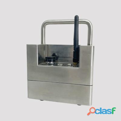
Overview The mold is a device that shapes the cast product in continuous steel casting, and it is also the core equipment and key technology of continuous casting machine. The main function of the mould oscillation deflection detection instrument is to detect the the mould oscillation table’s oscillation frequency, amplitude, deflection rate, phase, oscillation trajectory curve, etc. Through the detection and adjustment of the detection instrument, the mold moves along the outer arc of the continuous casting machine according to the set amplitude, frequency and waveform deflection characteristics. The actual oscillation parameters of the mold oscillation table during the production process and the process parameters of the cast products cannot be effectively known without the data detection of the mold deflection detection instrument, so that the operator cannot adjust the mould’s production process parameters in real time according to the real-time situation of the on-site production. The continuous casting mold deflection detection instrument independently developed by our company is suitable for various molds such as slab, square billet, round billet and shaped billet. The system obtains the process parameters such as actual oscillation holographic parameters and negative slip amount of the oscillation table by effectively detecting the movement of the mold. The technicians can formulate the control strategy of the mould according to these actual parameters, and improve the output and quality of the product within a safe and reliable range. The structure of the instrument Continuous casting mold oscillation and deflection detection instrument is mainly composed of sensor system, sensor signal conditioning circuit, power supply circuit, synchronous data acquisition module, communication cable, and software data analysis system. There are three axial acceleration sensors installed in the mold oscillation and deflection detection instrument, one of which is to detect the vertical oscillation signal (Y axis), and the other two are to detect the horizontal oscillation signal (X and Z axis). The signal obtained by the sensor is processed by the preprocessor and the preprocessing module. The oscillation signal and sensor status signal will be filtered and normalized, sent to the synchronous data collector for digitization and feature extraction, and the data is analyzed and processed by the master computer software to obtain various oscillation parameters and process parameters required by users. The functions of the system 1. Adopting mould oscillation X/Y/Z three-dimensional data acquisition, using high-precision sensor system and high-sensitivity axial accelerometer, comprehensive detection of equipment oscillation state, including: 1) Detect the oscillation frequency of the mold oscillation table 2) Detect the amplitude of the mold oscillation table 3) Detect the deflection rate of oscillation 4) Detect the lateral deflection, longitudinal deflection, phase, and phase difference of the mold oscillation table 5) Three-dimensional display of the oscillation trajectory, and the oscillation table trajectory can be viewed from 6 sides of the oscillation table (X-Y, X-Z, Z-Y) 2. The software system adopts the design of man-machine interactive graphic interface, which can display the mold oscillation state in real time. The software functions include: 1) Real-time data curve display: oscillation waveform, oscillation frequency, signal superposition analysis 2) Single-axis curve display, multi-axis curve display, amplitude, acceleration, three-dimensional graph 3) View historical curve 4) Generate test report 5) Give a warning prompt 6) Spectrum analysis function 7) Long-term storage of data 3. Portable measurement method, which can provide handheld detection equipment with wireless remote transmission, and the operation is simple. 4. Provide an overview of inspection parameters under the full screen, displaying all data including oscillation parameters and process parameters. At the same time, the calculation and display of the oscillation spectrum is completed in real time, which is used to evaluate the frame loss of the waveform , and to determine whether there is a problem with the installation of the oscillation device. 5. Alarm management. Record each alarm data under real-time alarm conditions to analyze the cause of the alarm and evaluate the impact of the alarm on production. 6. Parameter setting. Users can set the ideal oscillation value and normal working range of various steels online. We also can set the alarm limit, and the storage time of the database etc. 7. After charging the device once, it can work continuously for more than four hours. 8. Integrate embedded processing equipment to realize data collection, display, analysis, reporting and other functions. 9. According to the mold characteristics and user requirements, it can be flexibly configured, wich is suitable for all types of molds such as square billets, slabs, round billets and other mold oscillation tables. 10. Support wired and wireless data transmission functions, easy to use. 11. Use the laptop to receive the collected data, can be used for the operation test on site, and can analyze and process the data conveniently. The features of the system 1. The actual oscillation state replaces the ideal oscillation state. The actual oscillation state of the table is used to formulate a control strategy, so that the oscillation table can be used to produce products with more accurate oscillation. 2. Convenient detection method. The equipment can be used for on-site inspection at any time, and the production site can grasp the operating status of the on-site equipment in time, so that we can make production adjustments to the equipment at any time. 3. Efficient working methods and processing platforms. The high-integration equipment developed by embedded technology can work in high temperature and harsh environment. This system can comprehensively detect XYZ three-axis data, and realize real-time data analysis and processing with high-speed data operation and processing platform. 4. Powerful database function. The database adopts the mode of computer automatic management and operator's manual assistance management, and there are tables for recording historical data and alarm data and working parameter setting table of monitoring system inside the database. By adjusting the output range, the best output effect can be obtained.
Rs 0,0
See product