-
loading
Ads with pictures

Kojie

Top sales list kojie

No results found

Latest Offers

Pakistan (All cities)
Overview The all-digital non-touching infrared/laser automatic cut-to-length system developed by Wuhan CenterRise M&C Engineering Co., Ltd. is the first digital measurement, digital transmission, digital positioning and digital control technology in China. It is suitable for the primary and secondary cutting of continuously cast product of square billets, rectangular billets, slabs, round billets and shaped billets. It can automatically cut 1-24 strands billets to length at the same time, and display the casting speed and running status of each billet. The system has high measurement and control accuracy and strong anti-interference ability, which improves the output and quality of the cast products and reduces the labor intensity of the operator. The whole system has the advantages of low investment, simple installation, debugging and operation, and basically maintenance free. No need to change the original production equipment, a major breakthrough in the automatic cut-to-length cutting method, and it is also an important part of the continuous casting process, which has been highly praised by experts and manufacturers. Digital infrared cutting to length can also provide high-definition solutions, so that the measurement error is ±2mm, and the system can support 4 strands high-definition CCD image measurement. The features of the system 1. The system adopts advanced digital image processing technology (non-touching type) to identify the length of hot billet online, automatically controls the flame cutting machine to cut the hot billet to a certain length, detects and displays the running status and casting speed, and collects the image information of the moving billet from a long distance through an infrared camera. 2. The computer processes the image information by pattern recognition program, forms the operation information and converts it into the electrical signal of the specified format, so that the hot billet can be cut by the actuator. The system can cut the 1-24 strands to length at the same time with an infrared camera. 3. A schematic diagram of the overall layout and working principle of the system is shown in Figure 1. Fig 1 The functions of the system 1. Applicable to all kinds of continuous casting machine flame cutting system. 2. Adopt advanced digital image pickup technology. 3. It is not sensitive to other high-intensity light interference, and overcomes the influence of light sources such as sunlight and arc welding. 4. The system provides abundant interfaces, which can communicate with with the PLC. 5. The fixed-length parameters and data can be directly modified by the secondary system to optimize the fixed-length cutting. 6. Historical cutting data is automatically stored, and the system can set rules for historical data. 7. Support the free transformation of fixed length, and a variety of operation modes are available for the operator to choose. 8. Each stream can send out signals such as pre-clamping, clamping, cutting, roll-up, roll-down and return of the cutting car according to the user's requirements. 9. The monitor displays the running status of the current hot billet in real time and displays the corresponding parameters. 10. Data management can be carried out according to shifts, pouring times, days, weeks, months, etc., as well as data management according to specifications, production capacity, quality, etc. 11. Provide automatic, manual cutting control. 12. The detection and cutting precision is high, and the controllable precision is ±5mm. The extension of the system The system can install 1 to 8 cameras. Generally, when one camera cannot meet the requirements, the system can be equipped with 2 to 8 cameras. The camera can be fixed inside and outside the operating room perpendicular to the roller line, and the setting height is generally 3-5 meters, so that the camera can clearly and completely capture the image of the moving billet. High-definition line scan cameras can also be provided to perform high-precision positioning of each strand of cast products. Line scan cameras are used to support up to 12 strand systems, which ensures that the center of the viewing angle, the billet head, and the fixed-length mark are vertical to improve the cutting and fixed-length accuracy. The technical parameters 1.Numbers of caster stands: maximum 24 strands 2.Cutting method: flame cutting 3.Matching casting speed: ≤6.5m/s 4.Temperature range of billets: 1000℃ 5.Measurement accuracy: ±5mm 6.Cut-to-length range: 3-18m 7.Signal transmission: TCP/IP 8.Number of signals: pre-cut, cut
Rs 0,0
See product
Pakistan (All cities)
We are Manufacturer of garden benches. We have wide range of garden and Park benches with weather resistant, Durable and Long lasting. Widely used in Societies, University's, Farm house's. Delivery Available all across Pakistan. Contact us on What's App. [redacted phone number]
Rs 11.000,0
See product
Pakistan (All cities)
Overview Our company focuses on the production and application of the cables in continuous casting steel production. We have rich on-site usage experience, which provides us with technical guarantees for manufacturing high-quality communication cables. For cables of different applications, we have different protection requirements, such as high temperature resistance, anti-pull, acid and salt spray resistance, slightly positive pressure heavy-duty connector, anti-oil pollution, anti-interference, etc. Common industriaI cable for continuous casting 1. Breakout prediction compensation cable 2. Mold level control cable 3. Mold oscillation cable 4. VUHZ sensor cable 5. Mold width adjustment cable 6. Dynamic lightly depress the cable 7. Fixed cable for ladle slag 8. Movable cable for ladle slag The quality control All our products use proven materials to ensure stable and reliable product quality from the source. The core equipment all adopt imported raw materials. From raw material control to wire harness integrated processing, we ensure the stability and consistency of product quality. The scientific quality management system brings the product quality to a higher level. The program customization Our company has been focusing on the production and processing of wire harness products for many years. We have a professional technical team, which can realize synchronous development and technical docking with customers timely, optimize product design, and provide customers with complete solutions for wire harness products. Widely used: All kinds of wire harnesses produced by our company are widely used in major steel mills across the country, such as SHOUGANG, TISCO, HBIS GROUP, TIANJIN IRON PLANT, BAOGRANG GROUP, etc. The first-class product quality, and has won unanimous praise from domestic and abroad.
Rs 0,0
See product

5 photos

Pakistan (All cities)
Overview LDT-I200 is a new generation of converter lining thickness gauge launched by our company. The system equipment emits a pulsed laser beam to the lining surface of the converter, and receives the returned laser light to measure its flight time. Then the system equipment calculates the distance between the equipment and the target point according to the transmission speed of the laser. During measurement, the user pushes the equipment to a certain position on the platform in front of the converter, and the equipment can start to scan and measure the target area of the converter after the equipment performs rapid self-positioning. The Measuring principle The measurement speed of LDT-I200 can reach up to 2,000,000 points per second, and each scan can obtain distance data of more than 1.5 million points. The actual surface curve of the entire converter lining can be obtained by combining the measurement data of different positions and angles. During the measurement, the laser head of the equipment rotates at a certain step angle to rapidly change the angle of the pulsed laser beam. Within 4 minutes, the three-dimensional surface contour of the converter lining can be formed, and the thickness information of the furnace lining can be obtained through coordinate conversion calculation. The measurement accuracy up to ±2mm. In order to convert the distance from the internal point of the converter to the thickness gauge into the thickness of the furnace lining at each point, we must know the coordinate relationship between the trolley and the converter. We use the second laser head to position the trolley. When the trolley is pushed to the measurement site, the positioning laser head rotates at high speed to scan the three reflective strips opposite the converter. Through triangulation measurement and calculation, we can calculate the relative position of the trolley to the reflective strips. The coordinates of the reflective strip and the converter are known through mapping, so that the coordinates of the trolley relative to the converter can be accurately obtained. The main components 1. Laser measuring head 2. Wireless communication 3. Battery pack 4. Mobile laser thickness gauge host 5. Converter inclination measurement system 6. Cooling circulation system 7. Positioning auxiliary reflector 8. Laser positioning system The technical indexes Laser reproducibility: ±2mm Laser accuracy: ±2mm Local fastest measurement time: 15s Positioning time: 30s Full image measurement time: 4min The highest measurable lining temperature: 1850℃ Measuring distance: 0.5-25m Actual points are measured per frame: 1500000 points Continuous working time after fully charged: ≥3h Eye-safe laser: Class 1 laser product (doesn't hurt the eyes) The parameters of laser measuring head Measurement principle: According to the flight time and speed of the laser to calculate the distance Laser reproducibility: ±2mm Laser accuracy: ±2mm Scan rate: 2000000 points/second Measuring angle: vertical ±40°, horizontal 360° Maximum measurement temperature: 2200℃ Working temperature: -20℃-80℃ Cooling method: Integrated liquid cooling system, IP64 grade protection Laser wavelength: 1550nm (near infrared)
Rs 0,0
See product

2 photos

Pakistan (All cities)
Overview The surface quality inspection of high temperature cast product is of great significance to the repair of cast product’s defects and the hot delivery of hot cast product. The ZSQ-T series of online surface quality inspection equipment for casting billets developed by Wuhan CenterRise M&C Engineering Co., Ltd can detect the defects such as scratches, cracks, holes, pits, edge cracks, edge defects on the surface of the cast products, and meet the customer's requirements for the quality inspection of the surface of the cast product. The principle of the system The ZSQ-T200 online surface quality inspection system for continuously cast products adopts the principle of optical imaging and uses a CCD image sensor to input the surface image of the cast products to be detected into the computer, and then the obtained image is processed by special image processing software to find out whether there is any defect in the image. After the defects in the image are obtained, the obtained defects are classified through a special self-learning system, and finally the requirements of the computer to automatically identify the surface defects of the cast products are achieved. The composition of the system 1. Optical part: The optical part is composed of multiple fixed-focus lenses and linear CCD, which mainly realizes scanning and imaging of the surface of the cast products. 2. Lighting part: The lighting part is composed of a high-brightness LED array and a cylindrical lens, which realizes high-brightness and high-uniformity lighting on the surface of the cast products. 3. Mechanical structure part: The mechanical structure part mainly realizes the adjustment, installation and fixing of the optical part and the lighting part, and consists of the imaging head (optical part), light box (lighting part), bracket and control cabinet. The structure is required to be stable and reliable. 4. Real-time processing: The real-time processing part is completed by the multi-CCD data real-time sampling processing unit (high-speed DSP) independently developed by Wuhan CenterRise M&C Engineering Co., Ltd. 5. Hardware part: The hardware part consists of high-speed storage controller and storage hard disk array, Gigabit InternetMAC controller, Gigabit Ethernet PHY. Rj45, and multiple high-speed workstations. 6. Detection software: The detection software mainly realizes the functions of collection, storage, transmission, processing of CCD scanning images, extraction of defects, analysis of defect characteristics, calculation of defect size and position, storage of defect images, generation of cast product’s surface quality analysis reports. etc.
Rs 0,0
See product
Pakistan (All cities)
Overview MAC-G320 automatic mold flux feeding system is a new generation product of automatic adding mold flux, which is independently developed by Wuhan CenterRise M&C Engineering Co., Ltd. According to different steel grades, casting speed, vibration and other process parameters, then the system can analyze and calculate the accurate mold flux addition amount through intelligent software. Then the system sends out signals to control the mold flux addition process and mold flux addition amount, and designs appropriate nozzles and propellers according to the fluidity of molten steel in the mold and the ductility of mold flux. After the system setting is completed, there is no manual intervention is required. It completely replaces the whole process of manual addition of mold flux, and realizes the automation of mold flux addition. The features of the system 1. The system automatically controls the amount, process and time of adding mold flux according to the process requirements of automatic mold flux addition, so as to maintain the physical state of the mold flux and prevent it from being broken. 2. The user can match different parameters according to actual needs, so as to change the length of the mold flux feeding time and the amount of mold flux, which can suit for the use of different segments and different casting speeds. 3. The casting speed signal is used and the amount of adding mold flux can be automatically adjusted according to the casting speed. The mold flux can be added timely and evenly, which can improve the quality of the billet and reduce labor intensity. 4. The time is controlled by PLC, no manual intervention is required. The adjustment is very convenient. It has manual, automatic, local and remote control modes. 5. The system has reliable performance and simple structure, and can be adapted to powder and granular mold flux. 6. It has a special anti-blocking nozzle and backflushing design to overcome the phenomenon of pipeline blockage. 7. Strong operability, simple and convenient maintenance, and low maintenance cost. 8. It can maintain the even distribution of the flux layer in the mold. The composition of the system The system consists of feeding trolley, feeding bucket, swing arm and feeder motor, swing arm transmission device, PLC and control equipment. 1. The feeding trolley is the support and walking equipment of the mold flux feeder. The basic equipment of the adding mold flux machine is installed on the feeding trolley. At the same time, the trolley can easily make the mold flux feeder walk to the working position or the parking position. 2. The feeding bucket is a device for holding mold flux. The mold flux is pre-filled in the feeding bucket and is evenly output through the feeder. The feeding bucket is provided with alarm contact of mold flux level limit.. 3. The swing arm and the feeder motor form a feeding and conveying device. The mold flux is evenly transmitted to the feed opening at the front end of the swing arm through the screw distributing device controlled by the motor. Then the mold flux can be used for mold distribution. 4. PLC and control equipment adjust and control the mold flux feeding speed, operation mode and control mode of the mold flux feeding machine, and realize various control modes and rates. 5. The swing arm transmission device controls the reciprocating motion of the swing arm according to the size of different molds, so that the mold flux is evenly distributed in the mold. The technical parameter Mold width: 500-2000mm Mold thickness: 100-500mm Type: screw conveying type mold flux feeding machine Heating method: stirring electric heating Arrangement location: on the pouring platform (with its own wheels to move) Adding capacity: 0.5~7.5L/min, continuously adjustable feeding tube Molding flux storage tank: 300 L, with material level detection and alarm Control mode: local/remote control, automatic /manual mode Molding flux type: granular flux or powder flux flux adding method: spiral swing adding flux Casting speed interlock: yes Mould size setting: yes Signal transmission: DP/Industrial Ethernet
Rs 0,0
See product
Ahmadpur East (Punjab)
Online Silver Anklet in Jaipur – Chic, Elegant, and Comfortable Step up your accessory game with our gorgeous collection of online silver anklets in Jaipur at thelilacc. Crafted from 925 sterling silver, our anklets are designed to enhance your natural beauty with a perfect blend of sophistication and charm. Whether you prefer a simple design or one with delicate embellishments, our anklets add a graceful touch to any outfit, making them ideal for both everyday wear and special occasions. Why Choose Our Online Silver Anklets in Jaipur? Premium 925 Sterling Silver: Made from high-quality 925 silver, our anklets offer durability and a lasting shine that’s resistant to tarnish. Variety of Styles: From minimalist chic to ornate, detailed designs, our anklets come in a wide range of styles to suit your unique taste. Comfort and Fit: Designed for all-day wear, our anklets are lightweight, comfortable, and easy to adjust for a perfect fit. Perfect for Any Occasion: Whether you're dressing up for a celebration or adding a finishing touch to your daily look, our anklets are versatile enough for any occasion. Convenient Online Shopping: Browse and buy from the comfort of your home, with secure payment options and fast delivery across Jaipur. Shop online silver anklets in Jaipur at thelilacc and bring home the elegance and beauty of finely crafted silver jewelry. Order today and add timeless grace to your style!
Rs 3.541,0
See product

3 photos

Pakistan (All cities)
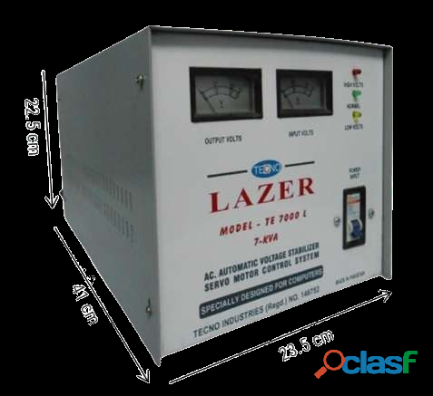
Manufacturer's Warranty. Tecno Industries (Reg) اَلحَمْدُ لِله Manufacturers of: SERVO MOTOR controlled, Automatic Voltage Stabilizers & Regulators. (pure copper) Since 1986 Tecno Lazer Pakistan. 0300-9433728 Ring Road, Band Road, Lahore Pakistan. A Servo Stabilizer That Decreases 30 Volts (back-from 250 to 220 & Increases 70 Volts from 150 to 220) (±) 1% {CAN STEP-UP from even low (on-demand)} اَلحَمْدُ لِله Runs your Equipment Even in Low Main Voltage. INFORMATION: 1: ( An Old Transformer / Relay carrying Stabilizer steps down or up after losing or gaining 20-25 Volts While A Servo Stabilizer steps down or up after losing or gaining 1 Volt. (±) 1%) 2: (on-demand) Buck-Boost Transformer Technology add-in 2kVA and above Models. Basically they work on DC Servo Motor Control system. Their efficiency is much better and its output voltage of either 110 or 220 AC or any required voltage, more-over TECNO 3Phase models up-to 500kVA ratings are manufactured against a confirmed order. 1 year warranty with parts. 100% genuine copper winding (GUARANTEED) Specs for (intelligent Voltage Stabilizer): SERVO MOTOR controlled, Automatic Voltage Stabilizers & Regulators. Input Voltage : 150 To 250 AC Output Voltage : 110v & 220v AC (±) 1% Frequency : 45 or 60 Hz Wave Form : Non-distorted Sine-wave Response Time : 25ms / V Efficiency : 95 % Power Factor : 0.95 Relative Humidity : 30% to 80% (without condensation) Temperature Rise : Less Then 50c Control System : DC. Servo Motor Insulation Resistance : More then 3M?? at 500V DC Tested : 1500 V We Manufacture Servo Motor Controlled Automatic Voltage Stabilizer, using Japanese technology, for UPS, Solar, AC Air-Conditioner, Split-Type, Window Type, (LCD/LED TV) Washing Machine, Treadmill, Photocopier Machine. Television, Music System, Refrigerators, Ultra sound Machines, Embroidery Machines, All Sensitive Equipment, Signalling Devices, CNC Machines, Air Conditioning Plants, Telecommunication Networks, Motor Loads, Data Processing Equipment, Bio Medical Equipment, Drives, PLC’s, Induction Heating, Hotels, Defence Application, Industrial Units, Lighting Loads, Residential/ Offices, Farm Houses, R & D Institutions, Mainline Stabilizers, Sophisticated Laboratory Equipment etc. Runs your Appliances Even in Low Main Voltage. وولٹیج سٹیبلائزر Standard Power Ratings Available in Single-Phase & 3-Phase: 500VA, 1kVA, 2kVA, 3kVA, 5kVA, 10kVA, 30kVA. Up-to 500kVA Punjab NWFP, KPK, & All Pakistan Cargo, Feel Free to Call: Rana Naeem Hammad. M.D. Tecno Industries (Pvt) Ltd Lahore. +923009433728
Rs 121,0
See product

11 photos

Pakistan (All cities)
Overview The continuous casting vibration type ladle slag detection device is used to detect the slag content of the ladle nozzle in the steelmaking continuous casting process, so as to improve the cleanliness of the tundish molten steel and obtain the best yield of the ladle molten steel. The device adopts the principle of vibration detection. The LAG-S200 continuous casting ladle slag automatic detection system is developed by Wuhan CenterRise M&C Engineering Co., Ltd. after many years of research with many scientific research institutes, and fully combined with the actual situation on site. It has a real field application value as a continuous casting ladle slag automatic detection system. The meaning of the system 1. Reduce the amount of tundish slag 2. Improve the purity of molten steel 3. Improve the life of the tundish 4. Reduce sliding nozzle erosion 5. Reduce nozzle blockage 6. Increase continuous pouring heats 7. Reduce the amount of residual steel in the ladle when high-quality steel is casting 8. Improve the yield of molten steel 9. Improve the quality of continuous casting billets In order to improve the purity of the molten steel in the tundish, and improve the quality of the casting billet, especially to improve the quality of the billet in the transition section, and reduce the amount of residual steel in the high-quality ladle, and prolong the life of the tundish lining, and increase the continuous casting heats, it’s necessary to detect and control the slag in the later stage of continuous casting ladle casting. The working principle The LAG-S200 continuous casting ladle slag automatic monitoring system detects the slag state during the pouring process by receiving the vibration signal of the mechanical operating arm of the ladle nozzle. In the process of molten steel pouring, when molten steel flows through the long nozzle and pours into the tundish, the molten steel impacts the wall of the long nozzle and causes the vibration of the mechanical operating arm used to support the long nozzle. Since the specific gravity of the steelmaking slag is less than half of the specific gravity of the molten steel, it floats on the surface of the molten steel, and the steelmaking slag appears when the molten steel is about to be all poured. At this time, due to the high viscosity and poor fluidity of light steelmaking slag, the impact force of the mixed flow of molten steel and steel slag on the wall of the long nozzle is quite different from that of pure molten steel. The system mainly monitors the ladle slag of the continuous casting by measuring and analyzing the vibration difference of the mechanical operating arm. The vibration signal is connected to the operation control unit of the system control cabinet through the front-stage conditioning and amplification module through the sensor installed in the middle of the operating rod. After processing, it is output to the industrial computer for operation and analysis. The slag signal detected by the system is output from the system control cabinet to the front-end control unit, and then control the alarm horn and alarm light to work, or issue an instruction to close the ladle nozzle. The features of the system (1) It is easy to install, basically no modification is made to the field equipment, and the installation and debugging work will not affect the normal production of the enterprise. (2) The detection accuracy is high, and the effective rate is greater than or equal to 95%. The threshold of slag volume is accurately set, the output control function is powerful. It has excellent performance in technical indicators such as the sensor service life and sensor usage times. (3) The sensor is installed at a position far away from the molten steel, and is cooled by a special refrigeration device for 24 hours. The outer layer adopts a composite protection structure, which has a long service life. (4) Adopt professional and targeted signal processing methods to obtain the vibration characteristic parameters of the ladle slag, and analyze, reason and judge the effective slag signal through the vibration signal database, which has a high accuracy of slag alarm. (5) The architecture is established based on the artificial intelligence network, which has the functions of self-learning and self-induction. (6) The equipment adopts a modular design. The failure of each module will not affect other parts, which ensure more reliable operation of the system and easy maintenance. (7) The alarm display device is used on site to visually indicate the flow state of molten steel and slag. When slag carryover strats, we can choose automatic mode or manual mode. In both modes, the system will give audible and visual alarm signals to remind on-site operators. (8) The system has a powerful database function. Including the comparison function for last two ladles of casting time record, the system automatically stores the running data, and generates a record file every day. (9) The system has the function of automatically controlling the ladle nozzle. The control unit is an auxiliary system of the system, which is interconnected with the ladle slag detection system to automatically control the opening of the ladle nozzle and realize the whole-process control of the liquid level of the molten steel in the tundish. The composition of the system The LAG-S200 slag detection system consists of: vibration detection sensor, pre-signal amplifier, slag detection operation unit, tundish liquid level control unit, on-site operation indication box, and process control cabinet. 1. Vibration detection sensor: It is installed on the robotic arm of the stopper to detect the vibration signal of the whole casting process of the ladle. 2. Pre-signal amplifier: Amplify, convert and transmit the weak vibration signal detected by the vibration detection sensor. 3. Slag detection operation unit: Analyze, judge and discriminate the vibration signal to realize the discrimination of all steel, mixed slag and full slag , and output the slag alarm signal. 4. Tundish liquid level control unit: Accept the control signal of the tundish nozzle and the ladle nozzle, and realize automatic or manual control to the ladle slag according to the requirements. 5. On-site operation instruction box: Provides man-machine exchange for slag alarm indication, fault indication, system activation mode selection, and control mode selection. 6. Process control cabinet, providing power management, displaying man-machine interface and setting management. The parameters of the system 1. The system controls the slag inclusion in molten steel with high precision and closes the nozzle in real time. 2. Improve the quality of steel, reduce defective products, and improve the yield. 3. The yield of molten steel is increased by 0.3%-0.5%. The nozzle can be automatically closed, so that the disadvantage of untimely manual response is overcome and less molten steel remains in the ladle. The threshold value of molten steel (slag threshold) is set by the user within a wide range. 4. No artificial factors are involved, high reliability, good repeatability or consistency. 5. The steelmaking slag does not pass through or rarely flows into the tundish, which increases the service life of the refractory material and the sliding nozzle. 6. Reduce the blockage of the tundish nozzle and increase the number of continuous pouring heats of the tundish.
Rs 200.000,0
See product

3 photos

Pakistan (All cities)
Overview The system realizes the fixed-length measurement of the width, thickness and length of the continuously cast product through machine vision and laser rangefinding system. The measured data is transmitted to the host system through the optical fiber. The host system calculates the weight of each billet according to different steel grades and specific gravity, so that we can realize the fixed length measurement and fixed weight control of the cast products and the precise control of the steelmaking process in the production process. After cutting the billets by fixed weight and length, the fixed weight cut-to-length system is checked by the online weighing measurement system, so as to give feedback to the fixed length model of control system. The slab number (automatic checking) can also be automatically identified online by using machine vision, and the weight and slab number can be automatically stored in the local database for use in the production and management system. The measuring principle of the system On the upper surface of the billet, a set of linear CCD cameras and a laser rangefinding instrument are respectively installed. Through machine vision and laser correction, we can achieve precise measurement of the cast products’ shape. Through accurate cast products’ shape monitoring, the billet thermal expansion coefficient of cast products and cast products’ density at the current temperature, we can obtain the quality of the billet. At the same time, we can achieve high-precision quality cut-to-length , namely, fixed-weight and fixed-length. The system can be matched with the weight detection and calibration system. The system adopts the online barrier-free hidden integral roller table weighing method for continuous casting products, and connects its weighing data into the intelligent control model. The model and steel billet weighing system, and the fixed weight cut-to-length system realize the closed-loop control of the system model, and optimize the fixed weight accuracy through automatic signal collection. The features of the equipment The cutting control technology for fixed-length and fixed-weight of cast products is a concrete manifestation of the lean production management of steel products. In the era of high-quality competition of steel products, only high-end intelligent technology and management can reduce costs, improve quality and market competitiveness. 1. Data management can be carried out according to shifts, pouring times, days, weeks, months, etc., as well as data management according to specifications, production capacity, quality, etc. 2. Each stream can send out signals such as pre-clamping, clamping, cutting, roll-up, roll-down and return of the cutting car according to the user's requirements. 3. The detection and cutting precision is high, the controllable length sizing accuracy is ±1mm, and the quality sizing accuracy is more than 1.5‰. 4. It is not sensitive to other high-intensity light interference, and overcomes the influence of light sources such as sunlight and arc welding. 5. The monitor displays the running status of the current hot billet in real time and displays the corresponding parameters. 6. Laser rangefinding and CCD machine vision are used to calculate the weight of the cast products and optimize the cutting to length. 7. Historical cutting data is automatically stored, and the system can set rules for historical data. 8. Support the free transformation of fixed length, and a variety of operation modes are available for the operator to choose. 9. Adopt advanced high temperature laser measurement and high pixel linear CCD technology. 10. The system provides abundant interfaces, which can communicate with the PLC control. 11. Applicable to all kinds of continuous casting machine flame cutting system. 12. Provide automatic, upper and manual cutting control. The main technical requirements 1. Width range of the inspected cast product: 120~2000 mm 2. Length range of the inspected cast product: 1000~20000 mm 3. Thickness range of the inspected cast product: 35~400 mm 4. Steel billet moving speed: 3.5 m/s 5. Billet running speed: 6.5m/min 6. Temperature of the measured steel billet: 0~850 °C 7. Measurement accuracy: width ±0.2mm thickness ±0.2mm length ±0.2mm 8. Fixed weight accuracy: 0.8‰ (temperature model verification) 9. Quality inspection check: 1‰
Rs 0,0
See product
Pakistan (All cities)
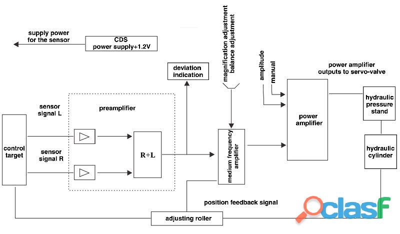
The composition of the system The photoelectric strip automatic center position control system is mainly composed of sensors, amplifiers, PLC controllers, hydraulic control and other parts. System composition block diagram The main technical parameters 1. Detection width: 300-2800mm 2. Detection light source: 220VAC. (100VAC) 30W. High frequency white light works continuously 3. Photodetector: precision die-casting components, time constant 20ms 4. Maximum working voltage: 50VDC 5. Distance from receiver to emitter: 300-1000mm 6. Operating temperature: 0℃-60℃ 7. Resolution: 0.5mm 8. Linearity: ±1%F.S (after linearization) 9. Repeatability error: △R1%, F.S 10. Servo-valve working signal: ±10V 11. Rated pressure (oil pressure): 4.5Mpa 12. Rated flow: 30L/min 13. Symmetry: 10%
Rs 0,0
See product

2 photos

Pakistan (All cities)
Overview Mold is the casting billet forming equipment in continuous steel casting, and it is also the core equipment and key technology of continuous casting machine. Its function is to forcibly cool the high-temperature molten steel continuously injected into its inner cavity through the water-cooled copper plate to export its heat and to gradually solidify it into a casting billet with the required cross-sectional shape and billet shell thickness. And the casting billet, which is still in liquid state, is continuously pulled out from the lower nozzle of the mold to create conditions for casting billet to be completely solidified in the subsequent secondary cooling area. The main function of the mould oscillation device is to make the mould perform mechanical movement according to the given characteristics of amplitude, frequency and waveform deflection. The purpose is to facilitate demoulding and prevent the occurrence of sticking and breakout accidents due to the bonding of the casting billet with the copper wall of the mold during the solidification process. MOC-K100 mould oscillation online monitoring system can three-dimensionally detect the positive and negative frequencies and waveform characteristics of the mould oscillation. The online changing data is provided in real time, which provides convenient and effective detection methods for on-site inspection personnel. The meaning of the system 1. When the continuous casting machine is not working properly, the billet quality problems (such as unstable oscillation marks, edge cracks, etc.) occur. According to the monitoring results of the system, we can combine with the actual on- site situation to analyze the cause of the failure, and efficiently evaluate and solve the problem of the oscillation table to improve product quality. 2. During the normal operation of the equipment, with the fatigue and wear of the mechanical structure of the mold, the expected oscillation parameters of the mold and the actual oscillation parameters will have a oscillation difference with time change, resulting in the internal process parameters’ changing of the continuous casting machine. Timely and accurate monitoring of changes in these parameters is helpful to schedule maintenance. 3. Transfer equipment maintenance from regular maintenance to state maintenance, do not repair when there is no problem, and arrange maintenance according to production needs when abnormal signs appear. Prevent over-repair and under-repair. 4. According to the monitoring results of the equipment, the on-site working parameters are adjusted in time to avoid adopting inaccurate or large-error oscillation to work and prevent the "breakout" accident. 5. We can timely find out that the oscillation is not stable or out of control in a small range, so as to avoid the formation of unevenness and unstable oscillation marks on the surface of the slab during the solidification of molten steel into the slab, and improve the surface quality of the product. 6. Adjust the working parameters reasonably according to the monitoring results, avoiding the use of excessive safety factor, making the entire assembly line play a normal working efficiency, increasing the output of billets, and create favorable conditions for increasing the casting speed. The functions of the system (1) Overview of monitoring parameters: Provides an overview of real-time monitoring parameters in the full screen, displaying all real-time data including oscillation parameters and process parameters. (2) Time domain waveform: This function mainly displays the oscillation waveforms of multiple measuring points and one channel standard waveform in real time, and simultaneously displays the three elements of oscillation of each measuring point in real time. (3) Waveform superposition: The difference between this function and the time domain waveform is that the waveforms of multiple measuring points are superimposed on a graph with lines of different colors on the same scale, and the oscillation difference of each channel can be calculated and displayed intuitively. (4) FFT: This functional module completes the calculation and display of the oscillation spectrum in real time. It is used to evaluate the waveform distortion of the entire oscillation table and to determine whether there is a problem with the installation of the oscillation device. (5) Bar graph: The oscillation of each measuring point is indicated by a bar graph of peak value and sensor gap voltage, which is more intuitive. (6) Trend: After starting this module, the operator can search the historical records in the database, analyze the changing trend of each parameter, and use it to analyze the rationality of the steel quality and processing parameter settings for different steels under the oscillation conditions. The parameters of the system 1. Number of measurement channels: According to the mold design, up to 16 sensors can be arranged 2. Sensor: three-dimensional oscillation sensing (X, Y, Z three axes) 3. Sensitivity: 1000mV/g 4. Frequency range: 0.04~10HZ 5. Frequency accuracy: ±0.01 Hz 6. Amplitude accuracy: 0.005mm 7. Transmission mode: wired digital transmission, wireless transmission 8. Host: 3U standard rack, handheld device 9. Sensor power supply: 24V.DC 10. Host power supply: 220V.AC/50Hz Mold oscillation curve The structure of the system The main components of the continuous casting mould online oscillation detection system are: 1. Three-dimensional oscillation measurement sensor 2. Handheld oscillation sensor calibrator 3. Dedicated signal connection cable 4. Preamplifier 5. Operation processing unit 6. Graphic display terminal 7. Industrial Ethernet (TCP/IP) or PROFIBUS-DP communication components 8. Control cabinet
Rs 200.000,0
See product

3 photos

Islamabad (Islamabad Capital Territory)
Starting a bakery business is thrilling, but success requires the proper equipment. The instruments you select will not only help you make high-quality baked items, but will also streamline your operations, increasing your bakery's efficiency and profitability. Here's a list of the basic bakery equipment from the Bakery Machinery Manufacturers, you'll require to get started the Successful Bakery Business. https://www.tradebrio.com/exporters/bakery-machinery.html
Rs 100,0
See product
Pakistan (All cities)
Overview: This product is a new type of mold copper plate surface detection equipment. The equipment adopts a high-precision and high-sensitivity laser ranging sensor, which scans the copper plate of the mould by scanning a laser line with a fixed width, and returns the measurement data in real time. After modeling and analyzing the data, the upper computer gives the wear data of the mold copper plate, as well as the data of surface cracks and surface flatness. The host computer software intuitively reflects the surface profile of the detected mold and thickness deviation and other data to the user in the form of data sheet, data curves and mold 3D model diagrams, providing a true and reliable theory for on-site operators to maintain the mold. The mold surface detection equipment is a high-precision instrument, which includes high-precision laser ranging sensors, two digital servomotors, encoders, horizontal sliding screws, vertical sliding screws, and calibration consoles, controllers and other components. The equipment has many advantages such as high accuracy, strong stability, convenient installation and strong observability. It is suitable for mold surface detection, surface flatness analysis, surface flaw detection, taper measurement, etc. It is also suitable for round billets, square billets, slabs, special-shaped billets, etc., widely used and powerful. The composition of the system: 1. The mold surface detection equipment is equipped with: data processing and display unit, horizontal motion mechanical power output unit, vertical mechanical power output unit, instrument motion control unit, laser measurement sensor, and instrument bracket. 2. Data processing and display unit: used for data acquisition and storage, system equipment control, parameter configuration, height display of the descent, start and stop control, etc. 3. Horizontal motion mechanical power output unit: the digital servo motor in the horizontal direction controls the sensor to move in the horizontal direction, so that the sensor can scan the horizontal inner cavity wall of the mold copper plate to detect data. 4. Vertical mechanical power output unit: the digital servo motor in the vertical direction controls the sensor to move in the vertical direction, so that the sensor can scan the vertical cavity wall of the mold copper plate to detect data. 5. Instrument motion control unit: It is used to control the motion scanning of the motor, and the running speed, running track, and control mode of the motor can be configured through parameter settings. 6. Laser measurement sensor: The laser displacement sensor adopts the principle of laser triangulation. The laser transmitter shoots the visible infrared laser to the surface of the measured object through the lens, and the laser reflected by the object passes through the receiver lens and is received by the internal line array image processing sensor. According to different distances, the corresponding positions of the light spots received on the line array sensor are also different. According to the angle of this reflection, the distance between the actual objects can be calculated by calculating the distance of the sensor spot. 7. Instrument bracket: The mold surface detection equipment need to be placed directly above the mold when it is in use, and it is required to be fixed firmly without displacement vibration during the measurement process to ensure the measurement accuracy. The parameters: Detection instrument service life: ≥5 years; Detection instrument reliability: more than 98%; Detection range: 60~1000mm (customizable) Detection accuracy: 0.01mm Spot diameter: 1.0x1.5mm (spot scan), 1.0x20mm (line scan) Falling pace: 1~20mm/step Single measurement time: less than 2min Power supply: DC24V Operating temperature: -20~80℃ Equipment warm-up time: 3~5min Shock resistance: 50G (X, Y, Z axis) Vibration resistance: 10Hz~5Hz (amplitude 1.5mm, each 2 hours in X, Y, Z axis)
Rs 0,0
See product
Pakistan
Top class litter of kc reg Akitas pups. Puppies have a fantastic blood lines and already chunky for their age.The pups have been flead and wormed up to date and are now on solid food. Puppies will be ready to leave for there loving homes
Rs 10.000,0
See product

Free Classified ads - buy and sell cheap items in Pakistan | CLASF - copyright ©2024 www.clasf.pk.